
Pog Plugs
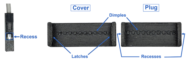
Pog Plugs are specifically designed to hold a group of Dupont connectors in place as a single unit, or “plug”. This effectively creates a plug, which can be removed and reinserted without having to connect/disconnect the Dupont connectors one at a time. There are two parts to the Pog Plug, the plug and the cover.
The plug’s dimples (see illustration) are aligned with the Dupont connectors’ recesses, and the cover is then clipped against the plug. This seats the clip’s dimples inside the connectors’ recesses, and ‘locks’ them in place, creating a sealed package. The entire plug, complete with all Dupont cables, is easy to remove and reinsert as a single unit. You can see a video demonstrating this here.
Pog Plugs are available from my Ko-Fi Shop.
GigaLab
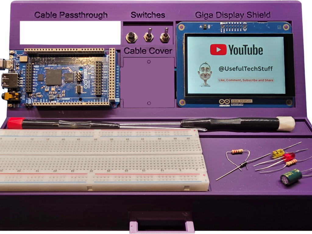
GigaLab Is a project born of necessity. It allows users of the Arduino Giga platform to use the Giga Display Shield alongside the Giga itself. No obscured connections, fiddly wiring or scratched display screen. The Arduino and display can now be used side-by-side. The GigaLab also offers a useful cable storage solution. You can download the 3D model for free, using this link.
The “Tester Tester”
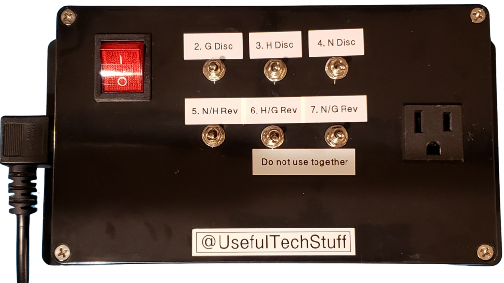
I cobbled this together just for a video I wanted to make (thus the crappy labelling). I made it to illustrate how limited a standard analog mains tester is, compared to its digital counterpart. The device was constructed so that I could “rewire” the outlet socket configuration by manipulating the switches. You can watch this video by clicking here.
The Experimental Lab
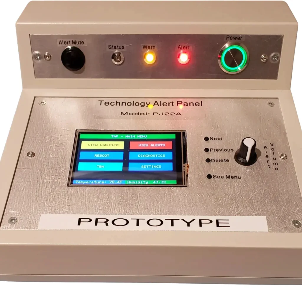
This started as a way for me to monitor the PCs on my home network. As projects do, it grew and grew, into a full-fledged system. This unit is based on an Arduino Mega with some additional electronics, including a real-time clock, themometer/Hygrometer, WI-Fi board, a buck converter, a LCD Screen, a SD Card holder, a relay, and a few other components. Here is an excerpt from the documentation I wrote, which should give you a brief overview.
This started as a way for me to monitor the PCs on my home network. As projects do, it grew and grew, into a full-fledged system. This unit is based on an Arduino Mega with some additional electronics, including a real-time clock, themometer/Hygrometer, WI-Fi board, a buck converter, a LCD Screen, a SD Card holder, a relay, and a few other components. Here is an excerpt from the documentation I wrote, which should give you a brief overview.
Experimental Lab (EL) has been designed to monitor Microsoft® Windows® computers (PC), on a home or office network. It does so by processing messages received from computers on a network and converting these messages into human-readable alert messages optionally, sounding an alarm inside the EL and/or, at the user’s discretion, activating an external device via a cable that provides a 5 VDC signal. At the user’s request, this voltage can be converted to 3.3 or 9 VDC.
EL Self-monitors network connectivity and will warn the user, should it no longer be connected to the network. There are also other built-in diagnostics.
EL Will alert users to local weather conditions that may affect IT equipment’s reliability, such as high winds and snow, which may cause power outages.
Proprietary software is installed on each PC to be monitored. The software consists of the EL Control Center and a Microsoft® Windows® service. Brief details of each of these software components are shown below. Please note that a separate manual is provided for the proprietary software.
The EL Control Center
This software allows the user to configure many aspects of the EL, including:
- Which messages should be sent to the EL (see service below), and:
- whether the status of the message is a Warning or an Alert
- should the internal/external alarm be sounded
- which lights should be activated on the EL control panel
- Some EL configuration settings
- Diagnostic Transmissions form
- Integrated help system
The Microsoft® Windows® Service
This service is responsible for monitoring the user-defined settings, as discussed above. As with most services, it remains constantly running in the background.
The Service can monitor many aspects of the PC it is installed on. These can include, at the user’s discretion:
- Memory Usage
- Disk usage
- Disk thrashing issues
- CPU Usage
- Specified services to ensure that they remain running
- Multiple other factors
The Experimental Lab – MK II
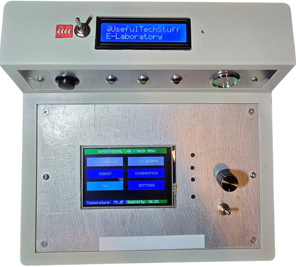
It occurred to me that this project could use a few more controls in order to improve its versatility, and for me to be able to change the data coming into the Arduino, and test various conditions within the software, without have to modify the code for debug purposes. It is the same unit as the one above, taken from a different angle and with different lighting. These are the changes I made:
- Added a warning buzzer on/off switch. This was to keep the family sane during my testing
- Removed the volume control and replaced it with a rotary encoder (for quicker selection of the received alerts – the buttons were previously used)
- Added a DIP switch. The Arduino reads these upon request
- Added a mini potentiometer (adjustment screw can be accessed by a small hole on the top). This serves the same purpose as the DIP switches, but provides the Arduino with an analog reading
- Added a two line LED. This is for debug messages and, depending on which button is pressed, displays the time and date or the value of the DIP switches, and the value of the potentiometer
- Added a switch to switch the two-line LCD on/off
Desktop Power Panel
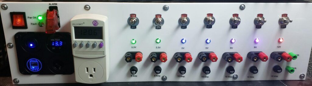
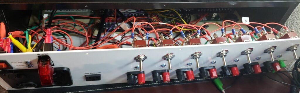
This one came about more as a fun project for me. I realized that when I used my lab power supply, it was nearly always on one of just a few voltages, so I set about building this fixed voltage power panel so that I could power things directly without having to adjust my lab power supply. The panel itself is, of course, self-explanatory. The Kill-A-Watt meter is powered separately from the panel, so as not to interfere with any readings. The black panel on the left is a car cigarette plug socket, for testing equipment which is fitted with / or comes with, such a connection.
Other Projects?
Oh yes, but these are the latest ones and I did not want to bore people too much.